Optical transmission hardware integration one-stop service provider

Views: 20 Author: Site Editor Publish Time: 2025-06-15 Origin: Site
With the rapid development of 5G, FTTH (Fiber to the Home), and data centers, the stability and performance testing of fiber optic networks have become critical. The OTDR (Optical Time Domain Reflectometer), as a core tool for fiber optic testing, can accurately locate faults, measure loss, and generate detailed link analysis reports.
This article will delve into how OTDR works, key parameters, selection guidelines, and real-world applications to help engineers, operators, and network maintenance teams improve fiber testing efficiency.
The OTDR (Optical Time Domain Reflectometer) sends light pulses into the fiber and analyzes reflected signals to detect:
✅ Fault locations (with meter-level precision)
✅ Loss distribution (connectors, splices, bending loss)
✅ Fiber length (supports single-mode/multimode fibers)
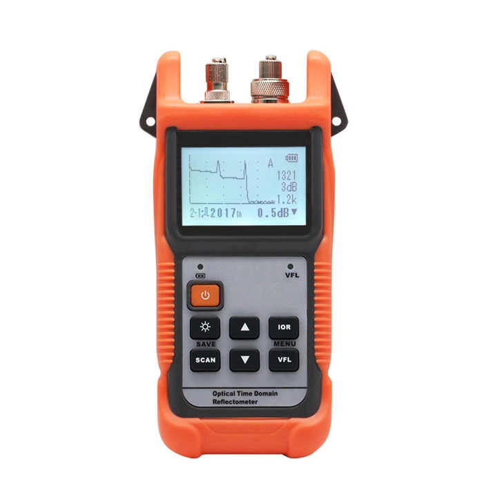
Laser pulse → Fiber transmission → Reflection at fault points → OTDR analysis → Event curve generation
Fresnel reflection (high-reflective events): Seen at connectors or mechanical splices.
Rayleigh scattering (continuous attenuation): Reflects inherent fiber loss characteristics.
When selecting an OTDR, focus on the following metrics:
| Parameter | Standard Requirement | Application Scenario |
|---|---|---|
| Dynamic Range | ≥35dB (long-distance) | Trunk lines, submarine cables |
| Dead Zone | ≤1m (short event dead zone) | High-density data center cabling |
| Wavelength | 1310nm/1550nm/1625nm | Single-mode (1310/1550nm), Multimode (850nm) |
| Pulse Width | 10ns~20μs (adjustable) | Short-range precision vs. long-range rough testing |
| Event Dead Zone | ≤0.8m | Identifying dense connections (e.g., patch panels) |
Case Study: A telecom operator used an EXFO FTB-1 OTDR (40dB dynamic range) to locate three microbend losses in a 5km fiber span, reducing troubleshooting time by 70%.
Tests: Splitter loss, home fiber splicing quality.
Recommended Device: Handheld OTDR (e.g., VIAVI T-BERD 2000) supporting PON wavelengths (1625nm).
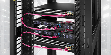
Challenge: High-density fiber jumpers prone to bending loss.
Solution: Use short dead zone OTDR to test MPO/MTP connector performance.
Challenge: Fault localization in intercity cables (≥100km).
Solution: High dynamic range OTDR (e.g., YOKOGAWA AQ7280) + remote collaboration software.
Requirement: Low latency, high-reliability testing.
Technology: CPRI/eCPRI protocol testing + OTDR link validation.
Single-mode or Multimode?
Single-mode: 1310/1550nm, ideal for telecom long-haul.
Multimode: 850/1300nm, for short-range data centers.
Need Automatic Analysis?
Advanced OTDRs (e.g., JDSU MTS-6000) auto-detect events and generate reports.
Budget Range?
Entry-level: $5,000~$10,000 (e.g., AFL FlexTester).
Industrial-grade: $20,000+ (e.g., Anritsu MT9083).
PON Testing Support?
Choose OTDRs with 1625nm wavelength to avoid service interference.
Portability Needs?
Handheld (fieldwork) vs. rack-mounted (lab).
❌ Issue 1: "Ghost" Peaks in Trace
Cause: Secondary reflections from strong reflective events (e.g., connectors).
Fix: Adjust pulse width or add an attenuator.
❌ Issue 2: Unable to Detect Short-Distance Events
Cause: Excessive dead zone.
Fix: Use short dead zone mode or reduce pulse width.
❌ Issue 3: High Loss Measurement Error
Cause: Incorrect refractive index (IOR) setting.
Fix: Calibrate fiber IOR (single-mode default: 1.468).
AI Analysis: Tools like VIAVI SmartOTDR auto-diagnose fault types (bend/break/contamination).
Cloud Collaboration: Real-time data upload for remote team analysis.
IoT Integration: OTDRs linked with fiber monitoring systems (e.g., RFTS) for 24/7 alerts.
From 5G base stations to submarine cables, OTDRs are essential for ensuring network reliability. Investing in the right OTDR can significantly reduce maintenance costs and improve efficiency.
Next Steps:
Define Needs: Choose a model based on testing scenarios (short/long-range, single/multimode).
Request Demos: Contact suppliers (e.g., EXFO, VIAVI) for hands-on trials.
Get Trained: Enroll in CFOS/T certification courses to enhance skills.