Optical transmission hardware integration one-stop service provider

Views: 1 Author: Ada Ru Publish Time: 2022-07-25 Origin: Site
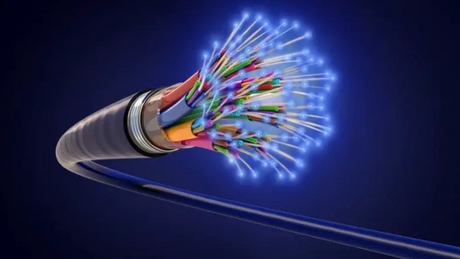
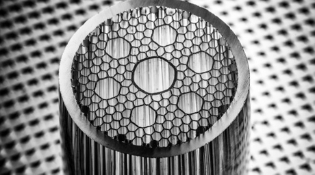
With the rapid development of local area networks and optical fiber access networks, the era of high-density optical fiber networks has come, and optical cables with large core counts, including ribbon optical cables, have been gradually adopted in the construction of communication networks. The use of multi-channel fusion splicing technology using ribbon fiber can save the cost of laying and bring good economic benefits [for example, in the access network project of optical fiber at the roadside (FTTC), the cost of single-channel optical fiber fusion accounts for 9%, while the use of ribbon The multi-channel fusion splicing of the optical fiber will save 60% of the cost of fusion]. There are many differences between ribbon fiber multi-channel fusion splicing and single-channel fusion splicing. Generally, optical fiber multi-channel fusion splicing has many differences compared with single-channel optical fiber fusion splicing.

The general single-channel fusion splicer allows the optical fiber to move three times in the V-shaped groove. The fiber core is aligned in one direction, while the multi-channel fusion splicer does not use the fiber core alignment technology, but adopts passive positioning technology, which only allows the fiber to move in one direction in the V-shaped groove, that is, only the end-face distance between the fibers in two directions is adjusted. In single-channel fiber splicing, in order to ensure lower splicing loss, an optical time domain reflectometer (OTDR) is used for bidirectional monitoring, while for multi-channel fiber splicing, due to the large number of cores, an optical time domain reflectometer (OTDR) is not used. Monitoring, direct blind connection. The advantages of multi-channel fusion splicing have led to the development of passive positioning fusion splicing technology. Passive positioning fusion splicing technology depends on the geometric size of the optical fiber to determine the splicing loss. Therefore, the geometric size of the optical fiber directly affects the actual fusion splicing ability. Concentricity and cladding straightness are the most influential. 1. Optical fiber warpage The optical fiber warpage refers to the degree of bending of the optical fiber along a specific length.
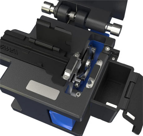
Excessive optical fiber warpage can cause excessive deviation in the multi-channel fusion splicer, resulting in high fusion loss. Fiber warpage can be measured by side-view microscopy to measure the fiber flat extension distance X and fiber offset. 2. Core cladding concentricity If the core is not in the center of the cladding, it will cause errors in the positioning of the core in various fusion splicers and connectors. Improving this parameter will significantly improve the fusion quality of the fiber and reduce the fusion loss. 3. Cladding Diameter Inconsistent cladding diameter will cause core positioning errors in passive positioning fusion splices and connectors. There are two types of fiber splicing losses. One is the internal loss caused by the characteristics of the optical fiber, but the external loss caused by the splicing process. quality. The following introduces the procedure of ribbon fiber fusion splicing and related matters needing attention. (1) Pull out the ribbon fiber from the optical cable and process a. Remove the loose tube of the ribbon fiber with a length of about 1M; b. Remove the cable paste with neutral solvent; c. Put the ribbon fiber on the optical tape Inside the clamp, keep it clean and have good clamping force. The optical ribbon fixture should be properly selected, and its width and thickness should be determined according to the number of cores of the ribbon fiber and the processing method of the ribbon fiber. Generally, the thickness of the coated ribbon fiber is about 400 microns, and the thickness of the bonded edge ribbon fiber is about 300 microns. . (2) Ribbon optical fiber stripping procedure The substrate and optical fiber coating of the ribbon optical fiber are removed by thermal stripping method: a. Put the ribbon optical fiber in the optical ribbon clamp into the thermal stripper (also called heating stripping pliers) Within 5-8s, the length of time depends on the substrate of the ribbon fiber and the fiber coating; b. After the fiber is stripped, a small amount of remaining coating material can be found on the surface of the fiber. Use lint-free tissue and more than 99% purity alcohol for cleaning. (3) Ribbon fiber cutting The cutting quality of the fiber is an important factor to ensure low splice loss. To maintain the good performance of the cleaver, the v-groove of the cleaver and the surface of the fiber must be kept very clean, the angle of the end face of the fiber after cutting is <1°, and the cutting length is 10mm. (4) Ribbon fiber splicing process a. The ribbon fiber is placed in the v-shaped groove, and the pre-melting arc burns off the impurities on the surface of the fiber, and checks the fiber end; b. Fusion; c. Check and test the arc strength of the fusion splicer before connecting, Find the best splice conditions and display the estimated splice loss (estimates are calculated based on the fiber-to-fiber end-face distance, the fiber end-face angle, and the alignment of the outer diameter of the fiber cladding). (5) Mechanical protection after welding a. When putting the sleeve on the welding point into the heater tank attached to the welding machine, the support rod in the sleeve should be placed below; b. Strengthen the welding point The protected fiber is installed in the splice box.
In order to achieve low loss in multi-channel fusion splicing, it is necessary to use optical fibers with excellent geometric properties, and operate in strict accordance with the prescribed procedures to ensure that the surface and end faces of the optical fibers are well treated. At the same time, attention must be paid to the cleanliness of the optical fiber, the environment and the instrument to keep the equipment in good performance.