Optical transmission hardware integration one-stop service provider


Views: 3 Author: Vicky Publish Time: 2023-07-31 Origin: Site
1
Q: What do the various diameter parameters in fiber optic patch cords represent?
A: These parameters are related to the fiber structure.
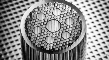
From the cross-section, the internal structure of the fiber as shown in the figure above, the corresponding parameters are interpreted as follows:
Core Diameter: Core is the actual transmission of light beams in the fiber medium, generally high refractive index materials (core refractive index > cladding refractive index), its physical diameter is generally between 2 μm-10 μm, the shorter the wavelength, the smaller the core diameter.
Mode Field Diameter (MFD, Mode Field Diameter): optical fiber using the principle of total reflection, but in fact, total reflection occurs, the light beam will pass through the boundary into the sparse medium to transmit a distance (known as the abrupt wave), and then reflected back to the light dense medium, the depth of the abrupt wave into the sparse medium and the wavelength of the wavelength is related to, and therefore can be found in the actual spot size will be larger than the core diameter, and this actual spot size will be larger than the core diameter, and this actual spot diameter is larger than the core diameter. Diameter, and this actual spot size is the mode field diameter, remember that the mode field diameter is not the actual physical size of the core diameter.
Cladding (Clad) diameter: the cladding refers to the immediate vicinity of the core and the core to form a high and low refractive index boundary so that the core in the transmission of light in the core of the total reflection of the medium, its diameter that is its physical size.
Coating layer diameter: because the core and cladding are glass materials, brittle, extremely easy to damage, so usually wrapped in a layer of resin outside the cladding to enhance the toughness of this layer of resin that is the coating layer, its diameter is the diameter of the coating layer.
Sheath diameter: because even if the optical fiber with the coating layer, in the external force is still easy to be folded under the damage. Therefore, in order to better protect the optical fiber and adapt to the use of complex environments, usually use additional plastic or metal sleeve on the optical fiber, sleeve diameter for its physical size. Commonly available are 0.9 mm, 2 mm, 3 mm, 6 mm plastic sleeves, or 3 mm, 6 mm stainless steel sleeves. lBTEK currently offers standard products with 3 mm loose sleeves, but other types of sleeves can be customized.
The above diameters are external diameters.
2
Q: When using a bias-preserving fiber optic patch cord, must the direction of incident light polarization be aligned with the slow axis to be bias-preserving?
A: No.
The direction of incident light polarization can be aligned with either the fast or slow axis of the patch cord to achieve polarization preservation, but there is a difference in the transmission rate.
3
Q: What is the damage threshold of fiber optic patch cords?
A: The damage threshold is related to the way of use.
The factors that limit the power of fiber use mainly come from the connector.
The structure of the fiber optic interface for the optical fiber (remove the resin coating layer, leaving only the cladding and core of the bare fiber) + epoxy resin glue + ceramic core, when the fiber is docked, limited by the docking accuracy of the connector, the fiber and the fiber core between the fiber can not be 100% aligned, the core of the core and the core of the core will have a certain degree of mismatch, this mismatch will lead to some of the light can not be coupled to the core of the fiber to be transmitted but was refracted outside the optical fiber by the epoxy resin glue. Absorption. The higher the beam power, the higher the optical power leakage, the glue absorbs the light cumulative energy and produce high temperatures, the glue shrinks due to temperature changes, the core and the core alignment error is greater, resulting in more beam refraction to the outside of the optical fiber cladding, and then make the glue volatile or even combustion (low ignition point of lipids). In addition, the glue melting or volatilization will condense on the fiber end face, blocking the light path, in the glue point to absorb a large amount of light energy ignition leads to fiber end face burned.
When using fiber optic flanges to assist fiber optic patch cord for docking use, for the working wavelength in 780 nm and above fiber optic patch cord, the maximum allowable power of 300 mW, and when the wavelength in the 780 nm below, the maximum safe power of 50 mW (this is because of the use of the epoxy resin on the shorter wavelengths of the light absorption is higher, and also because of the work of the fiber in the shorter wavelengths of the fiber core diameter is smaller, the same alignment) (a higher percentage of light energy is leaked by coupling accuracy errors).
When the fiber is used for output use or removed from the connector and fused using a fiber fusion machine, the power can reach more than 1 W.