Optical transmission hardware integration one-stop service provider

Views: 4 Author: Ada Ru Publish Time: 2022-05-30 Origin: Site
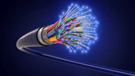
In an optical fiber transmission system, the optical signal will be attenuated with the extension of the transmission distance due to factors such as nodes or pollutants in the system, which is what we often call fiber loss. Optical fiber loss directly affects the transmission distance and performance of the optical fiber system. Therefore, we should always pay attention to the optical fiber loss of the optical fiber link in the transmission system. This tutorial will detail the fiber loss testing process for single-mode and multi-mode fibers. Tools for Fiber Loss Test Preparation Light Sources LED light sources and laser light sources are commonly used light sources in fiber loss testing.

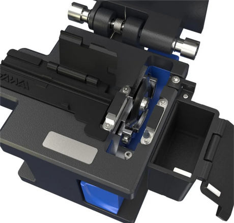
The LED light source is a light source with a light-emitting diode (LED) as the light source. Compared with laser light source, LED light source has wider bandwidth and lower output power, and its center wavelength is generally 850 nm or 1300 nm. The laser light source is an electric light source that uses excited particles to emit light under the action of stimulated radiation. The structure is relatively complicated, so the price is high. Its output power is about 10 times that of LED light sources, and its center wavelength is 850 nm, 1310 nm or 1550 nm, which is suitable for fiber loss testing applications of single-mode fibers. With the continuous development of photoelectric detection technology, PIN photodetectors are more and more used in optical power meters. There are three main types of PIN photodetectors in optical power meters: Si-PIN, Ge-PIN and InGaAs-PIN. Among them, the working wavelength of Si-PIN optical power meter is 850 nm, and the working wavelengths of Ge-PIN optical power meter and InGaAs-PIN optical power meter are 850 nm, 1310 nm and 1550 nm. Based on this, Si-PIN optical power meter has the lowest price. In general, Ge-PIN optical power meters and InGaAs-PIN optical power meters are commonly used in most fiber loss testing applications. Fiber Patch Cords and Adapters Fiber patch cords and connectors are tools used to connect optical power meters and light sources to the link under test. It should be noted that the core diameter and cladding diameter of the fiber jumper should be consistent with the fiber under test, and the fiber jumper should not be too long or too short, generally 1-3m. Also, before embarking on a test, inspect the connector on the patch cord with a microscope for physical damage. The importance of this step cannot be ignored, as physical damage to the connector directly affects the results of fiber loss testing. Not only that, since the connectors are divided into FC, LC, SC, ST and PC, UPC and APC, we should choose the connector type that matches the test equipment. Adapter selection is also critical because the alignment mechanism of the adapter has a significant impact on the test results.
Some poor quality adapters fail to align the fibers in the two connectors precisely after multiple uses, resulting in additional fiber loss. Here we recommend you to use high-quality adapters such as zirconia ceramics. Also, it is best to use the adapter less than 100 times for the most accurate test results. The most important thing to understand about the steps of fiber loss testing is that the fiber loss measurement measures the difference in power. For example, if we now want to test the fiber loss from point A to point B (as shown in the figure below), then the middle of the fiber link may be There are fusion splices or mechanical splices, but these are not our concerns when doing fiber loss testing. also. Before the optical fiber loss test, the working wavelength of the light source should be determined, and then the light source should be turned on and kept in this state for about 10 minutes to stabilize the optical signal emitted by it; then complete the loss test according to the following steps: Step 1: Measure the power when there is no optical cable to be measured (set the reference value), that is, connect the light source and the optical power meter through the optical fiber jumper and adapter described above, measure the optical power value at this time (such as -10dBm), and use this value as the value. Reference value (press the reference value key on the optical power meter at this time, and the screen of the optical power meter displays 0dB after pressing). Step 2: Disconnect the connection between the jumper and the adapter in the figure above, and the connection between the jumper, the light source and the optical power meter remains unchanged, and the light source and the optical power meter cannot be turned off. Step 3: Connect the free ends of the jumpers on both sides to the fiber to be tested, as shown in the figure below. At this time, the value displayed on the screen of the optical power meter is the loss value (such as 3dB) of the optical fiber link to be measured. This is the end result that the engineers want. Because optical fiber links have great advantages in meeting people's needs for high bandwidth, the use of optical fibers is becoming more and more extensive. Whether it is cabling construction personnel or network maintenance personnel, it is necessary to master the skills of optical fiber link testing. In addition, choosing a high-quality fiber loss test tool is also an important guarantee to ensure accurate test results.